When designing energy storage systems, we often ask clients about the proportion of inductive loads in their system and use this information, combined with other basic system parameters, to determine the system configuration. So, what are inductive loads? In simple terms, they are motor-based loads. In industrial settings, these include loads like water pumps and hydraulic systems, while in commercial settings, they typically involve air conditioners, elevators, and similar equipment. A key characteristic of these loads is that during startup, the inrush current can reach 3–7 times the rated current, causing a significant spike in the system's instantaneous load demand. Even with soft-start devices like variable frequency drives, the startup current can still be 2–3 times the rated current.
As we know, most current energy storage systems feature seamless grid-to-off-grid switching, with switching times typically ranging from 6ms to 20ms. Inductive loads, however, are highly sensitive. Even within such a short switching time, they may still require a restart, demanding immense instantaneous power from the system. When the system's capacity margin is limited, it may fail to complete the grid-to-off-grid transition, leading to system failure and an inability to smoothly support the load during grid outages.
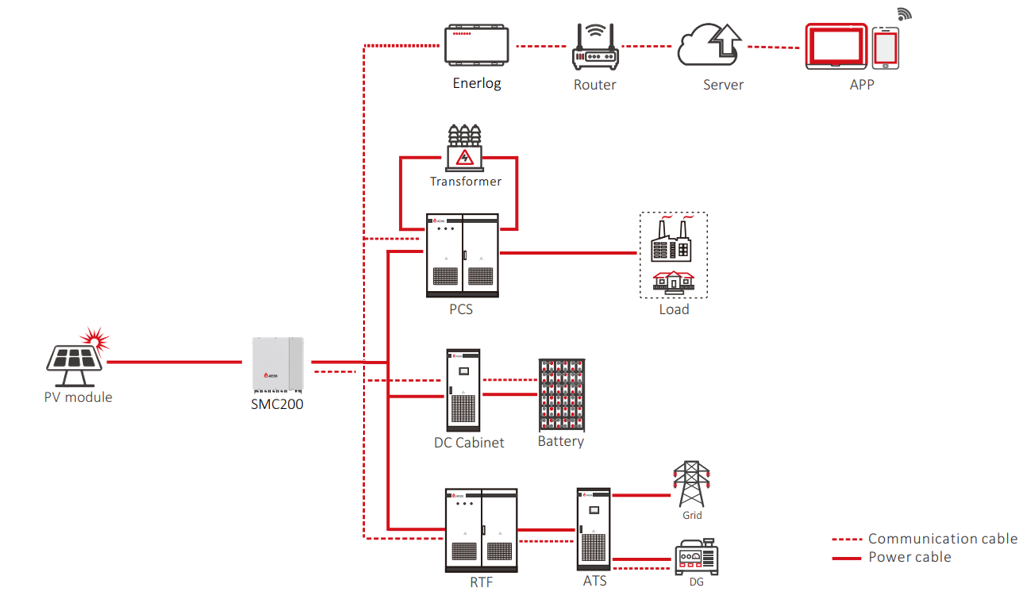
To address this issue, our company has introduced a novel DC-coupled solution, which we call the RTF solution. The name derives from a key component in this solution: the Rectifier Cabinet (Rectifier). This device can connect to AC power sources such as the grid or a diesel generator, rectify the AC power into DC, and feed it into the system's DC bus. The diagram below illustrates a typical RTF solution:
When the grid operates normally, the system can use grid power to continuously supply the load and charge the battery. In the event of a grid failure, the battery seamlessly takes over the power supply. Since the battery also outputs DC power, there is no need to switch between AC and DC, and the battery's discharge response is extremely fast—essentially a static or 0ms switch. This ensures that even inductive loads do not restart due to power fluctuations, achieving continuous and stable power supply. If the battery discharges to the preset State of Charge (SOC) and the grid has not yet recovered, the system, if equipped with a diesel generator, will automatically start the generator. The rectifier cabinet converts the generator's AC output into DC to take over the load supply from the battery. During this process, only DC-to-DC switching occurs, and the battery continues supplying the load until the generator is fully operational, ensuring seamless switching and uninterrupted, non-restarting load operation.
Let's now examine actual test data. The waveform diagram below pertains to a traditional AC-coupled system with an inverter output power of 500 kW, including a 400 kW inductive load. Theoretically, the 400 kW load does not exceed the inverter's maximum output capacity. However, due to the inductive load's startup current exceeding its rated current, the Power Conversion System (PCS) outputs a large inrush current, which triggers the inverter's overcurrent protection, leading to a fault state. As shown, during this switching process, the system's current and voltage are highly unstable.
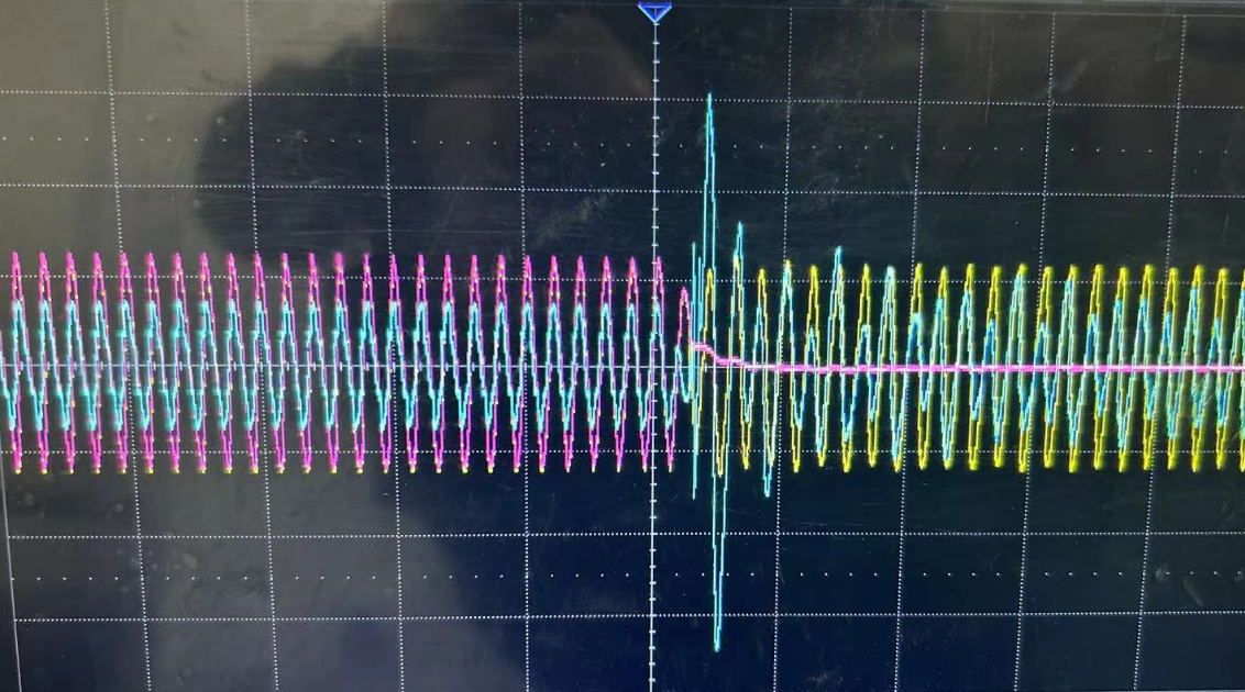
Yellow: PCS output voltage, Red: grid voltage, Cyan: PCS output current
With the same load conditions, the improvement after adopting our RTF solution is remarkable.
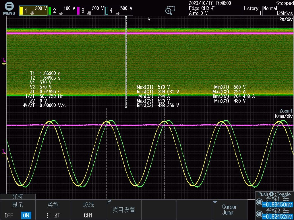
Yellow: Output voltage, Green: Output current, Red: Battery voltage
As evident, the system's voltage and current outputs are highly stable and consistent, presenting a clean sinusoidal waveform.
On the other hand, systems requiring an uninterrupted power supply typically include diesel generators as a backup energy source. Due to the characteristics of inductive loads and the varying performance of diesel generators, switching to generator power can sometimes result in excessive instantaneous load demand and switching failure. Let's look at another example:
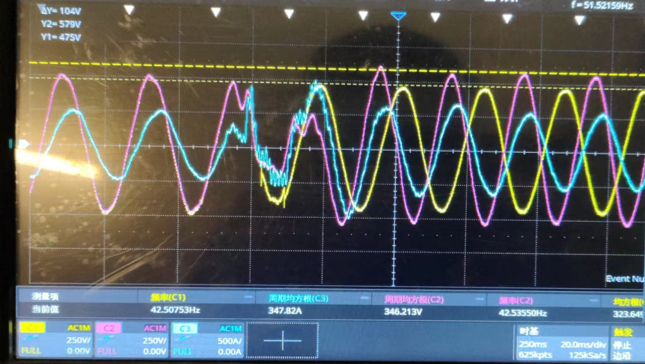
Red: generator voltage, Yellow: PCS output voltage, Cyan: Load current
The on-site diesel generator has a capacity of 250 kW, and the load power during the switch to generator mode is 150 kW. The moment the system switches to generator mode and the generator takes over the load, the generator's voltage collapses, causing the PCS to revert to off-grid mode. Only after the PCS enters off-grid mode does the generator's voltage recover. The reason: the generator's load-carrying capacity is poor, and its output response cannot keep up with the large power demand, leading to abnormal output.
In contrast, with our new DC-coupled system, the generator can gradually increase or decrease its output as needed, enabling smooth power source transitions.
In summary, this DC-coupled system, with all units operating in a single condition, significantly reduces switching on the AC side, avoiding output fluctuations caused by switching. This greatly enhances load operation stability, allowing systems with a high proportion of inductive loads to complete transitions more smoothly and achieve uninterrupted power supply.
If your system faces similar challenges, the RTF solution will help. Let's make your system no longer vulnerable due to “inductive” loads and transform it into a more “robust” solution.


