System Concept
Overview
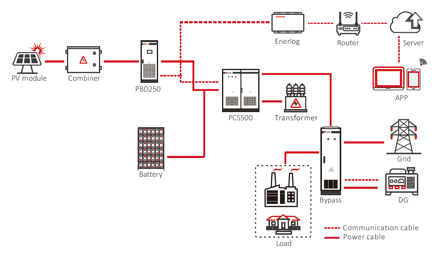
The ATESS DC coupling energy storage system aims to use the rectifier cabinet RTF to replace the bypass cabinet Bypass in ATESS' original AC coupling solution, thereby supporting the function of grid and generator access, changing the state switching logic of the grid and generator, and no longer carrying out the switching work on the AC side, eliminating the output fluctuation caused by the switching, thereby avoiding the risk of restarting sensitive loads. In the DC coupling solution, the energy storage system will serve as buffer power to achieve a completely smooth operation of the power system. This system is very suitable for large off-grid systems with a large proportion of inductive loads or with extremely unstable power grids and poor generator performance.
Schematic Diagram
New DC Coupling System
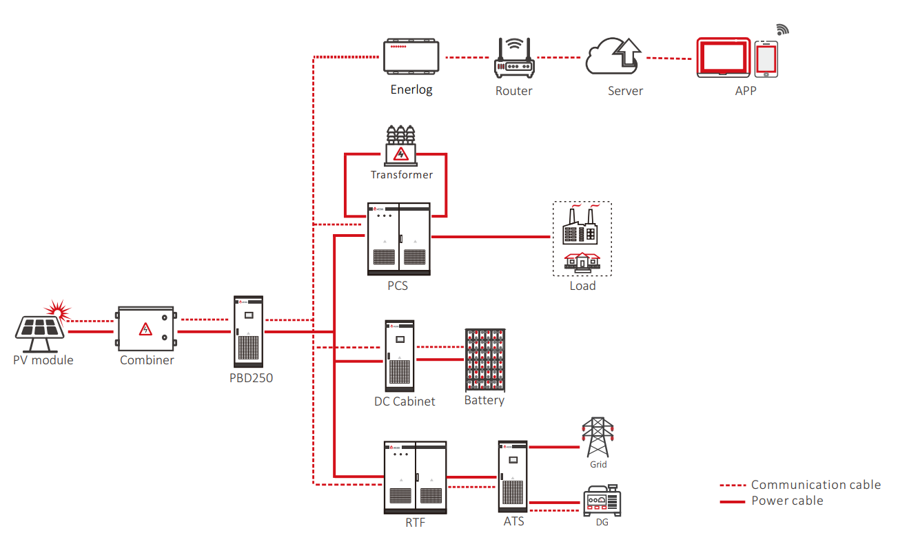
In this new DC coupling solution, the PBD output end, the DC side of PCS (bidirectional battery inverter), and the DC side of RTF (modular rectifier) share a DC bus, and all of them converge at the DC output side of the battery DC cabinet. PCS will continue to run in the off-grid mode as a VF source. It uses the CAN communication method and serves as the control host. By collecting status information of each unit, it controls the PBD, RTF, and power of batteries to achieve system functions and maintain the stable operation of the system.
PBD: Modular MPPT controller. It has 5 independent MPPT modules, each channel 50 kW. Single unit power up to 250 kW.
PCS: Bidirectional battery inverter. Single unit power ranges from 100 kW to 1000 kW (100/250/500/630/1000 kW)
RTF: Modular rectifier. Each module is 40 kW. A single unit can be configured with a maximum of 15 modules, and the power of a single unit is up to 600 kW.
ATS: Automatic Transfer Switch. The ATS is used to switch between the grid and DG automatically. It supports grid and generator access at the same time and has a single unit power of 630 kW or 1200 kW. With a built-in bypass switch, when the system fails, it can bypass the grid or generator to supply power to the load directly.
Parallel Solution:
ATESS PCS can be paralleled to increase the system load capacity (the maximum number of parallel units currently supported is 4.)
ATESS PBD can be paralleled to increase the PV access capacity (The number of parallel PBDs is theoretically not limited and ATESS will confirm the PBD parallel solution based on the actual situation of the project.)
ATESS RTF can be paralleled to increase the grid and generator rectifier power. (The number of RTFs in parallel is theoretically not limited. ATESS will confirm the RTF parallel solution based on the actual situation of the project. RTFs can be paralleled in different models to meet the needs of the project requirements, and currently RTF only supports the rectification function and does not support the inverter function.)
Original Bypass AC Coupling System
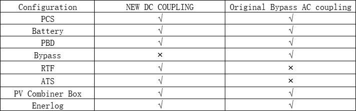
System Configuration Comparison
Applicable Scenarios
The power grid is extremely unstable—PCS is fully online and the load is not affected by power grid fluctuations
In the original PCS+Bypass solution, because the voltage or frequency is often unstable in certain countries and regions, the output voltage or frequency of PCS will fluctuate with the grid fluctuation and on-grid and off-grid switching will be performed frequently when the grid fluctuation is large and out of the range, which has a great impact on the stable operation of the loads. In this DC coupling solution, the PCS is not affected by grid fluctuations because it is always in the off-grid mode. Grid fluctuations only affect the output power of the ATESS RTF, and have no effect on the AC output of the PCS. And PCS output will continue to output according to the preset output voltage or frequency, thus greatly improving the stability of load operation.
Poor generator performance—PCS is fully online and the load is not affected by generator fluctuations
In the original PCS+Bypass system, due to the uneven performance of diesel generators, some diesel generators will have a sudden drop in output voltage when a heavy load is suddenly applied, resulting in the inability to normally switch to the diesel generator mode and a state of frequent switching back and forth, which has a great impact on the stable operation of the system and load. In this DC coupling solution, since the PCS is always in the off-grid mode and is not affected by the output fluctuations of the diesel generator, the RTF can control the power to increase slowly after being connected to the diesel generator, which to a certain extent avoids the voltage fluctuation when the heavy load suddenly is applied to diesel generator and has no effect on the AC output of the PCS. And PCS output will continue to output according to the preset output voltage or frequency, thus greatly improving the stability of load operation.
Complex load environment—Stronger inductive load adaptability
Load adaptability: Bypass AC coupling solution
When the system has inductive loads (such as water pumps, air conditioners, compressors, etc.), it needs to meet the following conditions:
| PCS100 | PCS250 | PCS500 | PCS630 |
the power of a VFD/VSD configured to a single motor (kW) | 10 | 10 | 10 | 10 |
the total rated power allowed by the motor (kW) | 5 0 | 1 2 5 | 2 50 | 3 15 |
the total maximum operating power allowed by the motor (kW) | 100 | 250 | 500 | 630 |
The total rated load power of the motor does not exceed 50% of the PCS rated power, and the maximum operating power does not exceed the PCS rated power.
When the rated power of a single motor is greater than 10 kW or greater than one-eighth of the rated power of the equipment, a VFD/VSD is required.
VFD/VSD requirements:
Voltage range -15% ~ +10%,
Frequency range 47HZ ~ 53HZ or 57HZ ~ 63HZ,
Overcurrent protection (When the current exceeds 150% of the rated power value over 60 seconds, the VFD/VSD activates the overcurrent protection function)
Load adaptability: New DC Coupling Solution
When the system has inductive loads (such as water pumps, air conditioners, compressors, etc.), it needs to meet the following conditions:
| PCS100 | PCS250 | PCS500 | PCS630 |
the power of a VFD/VSD configured to a single motor (kW) | 10 | 10 | 10 | 10 |
the total rated power allowed by the motor (kW) | 70 | 175 | 350 | 441 |
the total maximum operating power allowed by the motor (kW) | 100 | 250 | 500 | 630 |
The total rated load power of the motor does not exceed 70% of the PCS rated power, and the maximum operating power does not exceed the PCS rated power.
When the rated power of a single motor is greater than 10 kW or greater than one-eighth of the rated power of the equipment, a VFD/VSD is required.
VFD/VSD requirements:
Voltage range -15% ~ +10%,
Frequency range 47HZ ~ 53HZ or 57HZ ~ 63HZ
Overcurrent protection (When the current exceeds 150% of the rated power value over 60 seconds, the VFD/VSD activates the overcurrent protection function.)
Test Data Comparison
Switch Between On-grid and Off-grid Mode—Original Bypass AC Coupling Solution
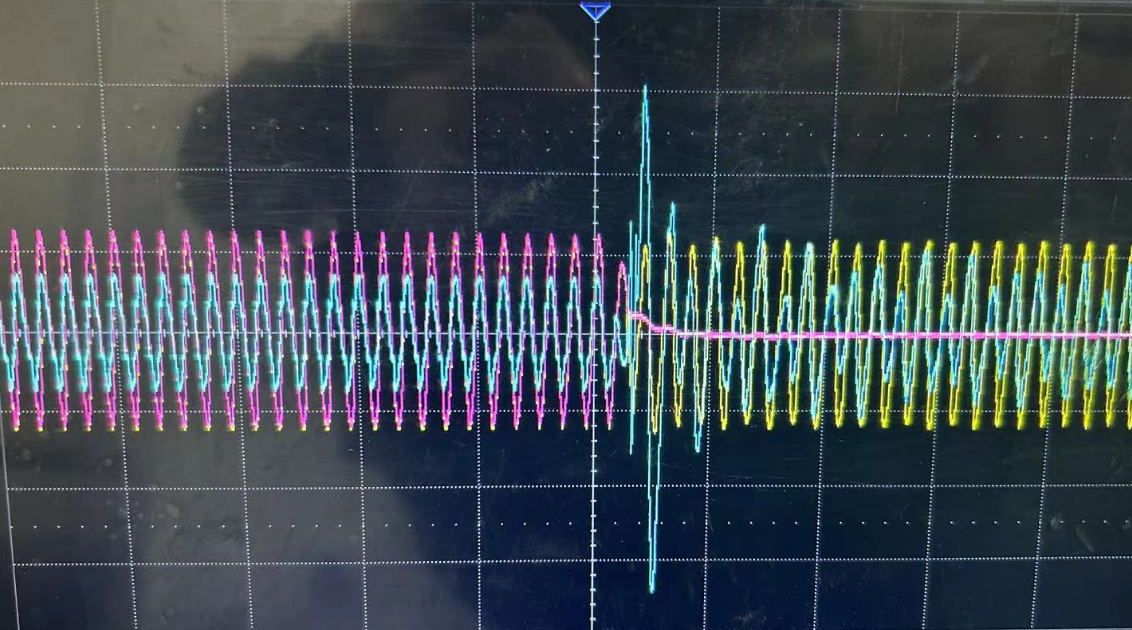
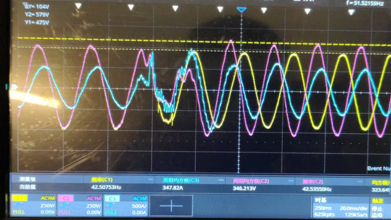
Yellow: PCS output voltage, Red: grid voltage, Cyan: PCS output current
Figure 1 above shows the waveform diagram when the PCS 500 is used to run an inductive load of 400 kW, the power grid fails, and the PCS switches to the off-grid mode. During the mode switching process, since the switching needs to identify power grid abnormalities before responding to the output, a voltage drop process will inevitably occur. Under the heavy load, this response time will be longer. During this process, some sensitive loads may restart. If the restarted load is from a motor, it will cause the PCS to output a large inrush current. If this current is too large, it will directly trigger the PCS to enter the fault state of overcurrent protection.
With the new DC coupling system, such switching problems can be avoided directly.
Switch Between Off-grid and Generator Mode—Original Bypass AC Coupling Solution
Red: generator voltage, Yellow: PCS output voltage, Cyan: Load current
Figure 2 above is the waveform diagram of the PCS250 on-site diesel generator with a capacity of 250K and a load power of 150K when it switches to the diesel generator mode. When entering the diesel generator mode and the diesel generator takes over the load, the diesel generator voltage drops and the PCS re-enters the off-grid operation mode. After the PCS enters the off-grid mode, the diesel generator voltage returns to normal. Reason: The on-site generator has poor load resistance. When high power is put into the load, the output response of the diesel generator cannot keep up, resulting in abnormal output.
Adopting a new DC coupling system, the need to gradually increase or decrease the output of the diesel generator can be realized.
Switch Between On-grid and Off-grid Mode—New DC Coupling Solution
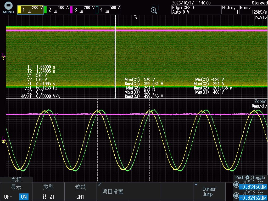
Yellow: Output voltage, Green: Output current, Red: Battery voltage
The above Figure 3 is the waveform when PCS switches to the off-grid. When adopting the DC coupling solution, the PCS AC output maintains off-grid operation when it is loaded. When the state of the system changes between on-grid and off-grid, there is no switching between various states like in the original AC coupling solution. Therefore, it is very easy to avoid system instability problems caused by external factors such as switching or diesel generators.
System Operation Strategy
Grid Online Mode
- - “PV power + grid power ≥ load power”, grid charging power can be set.
Note: If the charging cut-off SOC is 95 % and the grid stops charging when it reaches 95%, the system needs to be able to judge whether the grid is charging or the PV is charging. If the grid is charging, the charging cut-off SOC will take effect. If the PV is charging, then it must be “PV power > load power” under this condition. For example, the load power is 20 kW, the PV power is 30 kW, and the battery charging power is 30 kW. When the real-time SOC does not reach the charging cut-off SOC set point, the grid and the PV charge the battery together until the real-time SOC reaches the charging cut-off SOC set point, the grid stops charging, and the excess PV continues to charge the battery to the charging cut-off SOC.
- - PV power > load power, the PV is loaded and charges the battery;
-- PV power < load power, PV and battery are loaded together until the battery is discharged to the discharge cut-off SOC, and then the grid takes over the load. In this mode, the grid does not charge the battery, but the SOC needs to be maintained at the discharge cut-off SOC.
- -Level 1 Setting: Off-season and peak-season
-- Level 2 Setting: Month period of off & peak-season
-- Level 3 Setting: Weekdays, Saturdays, Sundays
-- Level 4 Setting: On-peak period, off-peak period, mid-peak period
Note: The on-peak period corresponds to the standard mode, the off-peak period corresponds to the back-up mode, and the battery does not charge or discharge during the mid-peak period.
Grid Offline Mode
-- PV power> load power, the PV is loaded and charges the battery;
-- PV power < load power, PV and battery are loaded together until the battery discharges to the diesel generator to start the SOC, and then the generator supplies power to the load. The function of the generator to charge the battery can be set, and the charging power can be set, and the diesel generator supplies power to the battery until the diesel generator shuts down the SOC. The conditions for starting and shutting down the diesel generator should take into account the SOC and should also include a one-key start and stop function that commands can be issued remotely through the server to start or shut down the generator.
Note: After the diesel generator is started, the mode displays as diesel generator online.
How to Configure
Generally, we recommend that the RTF power should be greater than the peak load power. In this situation, if there is no PV or when the battery capacity is low, the grid or generator can supply the load through the RTF and PCS, and at the same time, there is a certain amount of residual capacity to charge the battery. However, the configuration plans may also change due to different project requirements, and in such cases, it is advisable to consult with ATESS Pre-sales engineers to provide the correct configuration plan.
Summary
As each unit is in a single working condition, this DC coupling system greatly reduces the switching operation of the PCS on the AC side, avoids AC output fluctuations caused by switching, and greatly improves the stability of the load operation. Because the PCS continuously operates in the off-grid mode, the output voltage or frequency is not affected by the fluctuations of the power grid or diesel generator, and can maintain voltage or frequency stability, ensure the power quality of load operation, and improve the stability of the system.


