Energy storage deployment is shifting from MWh-scale installations to massive GWh capacities.
As system scales grow, mitigating thermal runaway risks and preventing battery lifespan degradation have become paramount engineering challenges.
Today, thermal management primarily splits into two distinct paths: air cooling vs liquid cooling. Each method offers unique trade-offs in terms of cost-effectiveness, heat dissipation efficiency, and footprint density.
This article compares these two thermal management strategies, helping you determine which architecture fits your project.
How Each Technology Works
1. Air-Cooling Technology
Air cooling uses fans to drive airflow through the gaps between battery modules. Heat leaves the cells by forced convection, a straightforward approach that keeps mechanical complexity and upfront hardware cost low.
Air has poor thermal conductivity and limited heat capacity, which makes precise temperature management increasingly difficult as power density grows.
2. Liquid-Cooling Technology
A liquid cooling system circulates a fluid, usually a water–glycol mixture, through sealed channels in a cold plate directly bonded to the battery modules.
Because liquids have a much higher volumetric heat capacity than air, a liquid cooling system can absorb and remove significantly more heat per unit of flow.
The result is tighter temperature control across every cell in the pack, both during normal cycling and during thermal stress events.
4 Core Dimensions Comparison
1. Thermal Performance and Temperature Uniformity
The heat transfer coefficient of a liquid cooling system is significantly superior to that of air cooling.
The thermal conductivity of liquid is approximately an order of magnitude higher than that of air, enabling rapid heat extraction from the cell surface, a critical advantage in high-rate charge/discharge applications.
More importantly, a liquid cooling battery provides exceptional control over temperature uniformity within a battery cluster. The cold plate design ensures even temperature distribution across each cell's contact surface, minimizing intra-cluster temperature differences.
In contrast, air cooling is constrained by the low specific heat capacity of air and complex flow paths. Cells located farther from the fans often suffer from inadequate heat dissipation, creating localized hot spots and accelerating cell inconsistency and degradation.
2. Energy Consumption and Economic Viability
Air cooling offers a lower initial investment, controllable fan and air duct costs, and requires no complex pipeline sealing or leak-prevention designs.
However, its long-term energy consumption is considerable: due to low air-side heat exchange efficiency, maintaining equivalent cooling performance demands sustained high airflow, resulting in substantial fan power consumption over time.
A liquid cooling system entails higher upfront costs due to components such as cold plates, circulation pumps, chiller units, and coolant, as well as stringent sealing requirements that increase manufacturing complexity.
Nevertheless, its superior heat exchange efficiency significantly reduces auxiliary power consumption, making the total cost of ownership over the full lifecycle often favorable for large-scale projects.
3. Environmental Adaptability
Air cooling is more sensitive to ambient conditions.
In regions with high sand/dust, high humidity, or severe salt-fog corrosion, large volumes of incoming air carry particulates, moisture, or corrosive agents that contaminate the battery compartment and accelerate component aging. High-grade filtration adds flow resistance and further increases energy use.
A liquid cooling system operates as a closed-loop circuit where the coolant is isolated from the external environment. This design delivers stable performance under extreme heat, sub-freezing temperatures, high humidity, or heavy sand/dust conditions, offering far greater environmental robustness.
4. Integration Density and Land Footprint
Thanks to its superior heat transfer capability, a battery liquid cooling solution allows for a much more compact cell arrangement, reducing the cooling channels required between battery clusters and thereby increasing system energy density.
For an equivalent energy capacity, the footprint of a liquid cooling system is typically significantly smaller than that of an air-cooled system, a critical advantage for urban commercial and industrial projects where land costs are high.
Air cooling requires ample airflow clearance between clusters, resulting in lower integration density and a larger overall land footprint.
Choosing the Right Architecture for Your Project
1. When Air Cooling Makes Sense
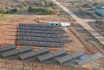
Small-scale microgrids, light commercial installations, and any energy storage project with daily low-rate cycling, such as solar self-consumption, can operate reliably with air cooling, particularly where the ambient climate is temperate, and the capital budget is tight.
Simplicity of maintenance and lower spare-parts dependency are genuine advantages in remote or low-resource settings.
2. When a Liquid Cooling System Is the Right Call
Large utility-scale plants, frequency regulation assets, fast-charging station buffers, and C&I energy storage projects with constrained footprints all benefit materially from a liquid cooling system.
So do any projects sited in hot, dusty, or high-humidity environments where an open-air thermal design would require constant filtration and cleaning.
In these scenarios, the investment in liquid cooling technology pays back through reduced degradation, higher throughput, and longer service intervals.
Liquid Cooling System from ATESS
For large-scale energy storage projects, high-rate applications, or deployments in demanding environments, the ATESS 20HCL 5MJ is purpose-built for the job.
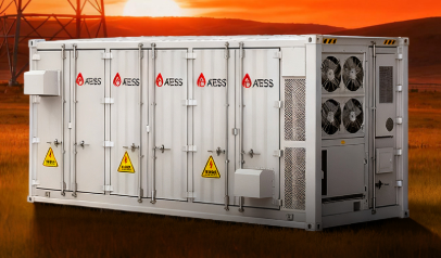
This 20-ft liquid-cooled ESS container integrates 5.015 MWh of capacity with a fully enclosed liquid cooling system, maintaining cell-to-cell temperature variation within 3°C across the full operating range, which contributes to longer battery cycle life and stable round-trip efficiency.
The design consolidates battery packs, EMS, BMS, HVAC, and an active fire suppression system into a single cabinet, reducing on-site installation complexity, lowering civil works costs, and simplifying long-term maintenance.
The system achieves IP54 protection at the system level and IP65 at the pack level, with C4 corrosion resistance, supporting reliable outdoor deployment in high-humidity, coastal, or high-sand environments.
Whether deployed on the generation side, grid side, or for C&I peak shaving, the 20HCL 5MJ delivers consistent thermal stability and high power density under sustained high-rate charge and discharge cycles.
Conclusion
As energy storage projects scale up in both capacity and cycling intensity, thermal management architecture becomes a defining factor in long-term system performance. Liquid cooling has become the enabling technology for the next generation of large-scale, high-performance energy storage. For project-specific guidance on grid services, industrial peak shaving, or renewable co-location, contact our team today.


